Scene Graph and model elements
Scene Graph and model elements
Scene graph
A scene graph is a tree of different groups of objects that are used to form a complete image (light sources, geometry, other auxiliary elements).
The geometry that makes up the model elements is also included in the scene graph, but the graph nodes responsible for the geometry of the model elements DO NOT repeat their list and DO NOT correspond with it. That means model elements are not identical to graph objects.
Working with the list of model elements or individual elements and their geometry is not done with the scene graph, but with the special functions of the SceneToolsclass, included in SceneManager.
Basic graph structure
The root of the scene is accessible through the sceneproperty of the SceneManagerclass.
Initially, an empty scene has a base graph consisting of several groups, in which objects will be added. Each group is also represented in the SceneManagerclass.
- groupLights - a group for light sources.
- groupElements - a group for storing objects that contain geometry of model elements.
- groupOpaque - a child group for storing objects that contain opaque geometry of model elements.
- groupLines - a child group for storing objects that contain linear geometry of model elements.
- groupTrans - a child group for storing objects that contain transparent geometry of model elements.
- groupPhantoms - a child group for storing objects that contain transparent phantom geometry of model elements (for example, rooms).
- groupEdges - a group for storing objects that contain geometry of model elements edges (reserved for future use).
Objects from groups are rendered in the order specified in the list. In the process of rendering the frame and its auxiliary passes, the renderer makes adjustments, enabling/disabling individual groups.
Model elements and their geometry
All elements contained in models can be divided into 2 groups:
- Unique elements - if an element in the model is unique (e.g., all slabs and walls in Revit are unique elements, even if they are copied across multiple floors).
- Repeating elements (instances) - if an element with the same geometry is placed many times in the model with a different location, rotation, scale, or reflection (for example, all Revit point families and their variations in the model are instances).
- These two types of elements store their geometry differently in the scene and work with them differently as well. We can say that they produce two kinds of geometric objects in the scene graph:
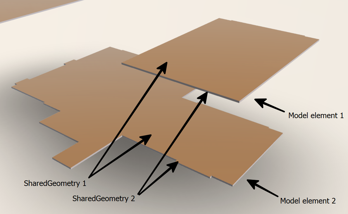
- SharedGeometry - geometry of unique model elements.
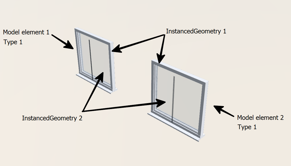
- InstanceGeometry - geometry of repeating model elements.
As the scene manager loads, it analyzes the instances in the model and may convert some of them to unique elements at its discretion, in order to provide an optimal level of rendering performance for the scene.
The physical division of geometry does not correspond to the logical division into model elements and is carried out according to different principles for different types of geometry.
Unique geometry is decomposed solely by material type.
Thus, one SharedGeometry object can contain geometry of several model elements with the same material or their parts with the same material. If a model element contains several materials, its parts will be contained in several SharedGeometry objects.
Type geometry is decomposed by material type within a single instance type.
Thus a single InstanceGeometry object can contain all instances of type elements corresponding to a particular type and material. If model type elements contain multiple materials within the same type, then their parts will be contained in multiple InstanceGeometry objects.
If the geometry has material with transparency, it is placed in the GroupTransgroup, otherwise in the GroupOpaquegroup.
All linear geometry (lines and segments) is also unique and falls into the GroupLinesgroup.
Internal model element identifiers and connection to geometry
While loading models, the viewer generates a unique numeric identifier, ElNum, for each element. This identifier is used to associate the element with its geometry and its metadata, as well as its global identifier (GUID).
ElNum is generated each time the model is opened in the viewer and in different model sessions and can theoretically be different each time.
ElNum is written to the attributes of all geometric objects, allowing you to always know which part of the geometry belongs to which model element.
To quickly bypass the scene geometry and work with it, according to model elements, the scene traversal functions described in a separate article are used.
Additional geometric data for elements
While exporting and loading models, the scene manager generates some data related to its geometry for each model element. Such geometry data can be found in the elementDatasproperty of the SceneManager class.
The property is a map where the element number ElNum corresponds to the ElementDataobject that stores the geometry properties of the element (for example, its bounding box).