Getting started with Tangl Control
Getting started with Tangl Control
Are you just starting to work with Tangl Control and don't know where to start, where to look and how to better understand the philosophy of the Control service?
Let's start from the very beginning, when you only have a BIM model, to the end, when you get the first results of its processing.
In this guide we will not delve into the complex mechanisms of analysis or the subtleties of the functionality and meaning of each option, but will try to understand the very essence and basic fundamentals.
Before going through this tutorial, install the client.
Client installation (article will be soon)
Also install the plugin for Autodesk Revit and see how to send models to the platform using it.
Model import from Revit (article will be soon)
If you don't use Autodesk Revit or you don't have it, you can see how to send an IFC model.
Model import in IFC format (article will be soon)
You can also send Excel files. They will be perceived as models without geometry, but with the properties of objects.
Import from Excel (article will be soon)
Running and viewing the model
Find the shortcut of the installed Tangl Control client on the desktop and run the program.
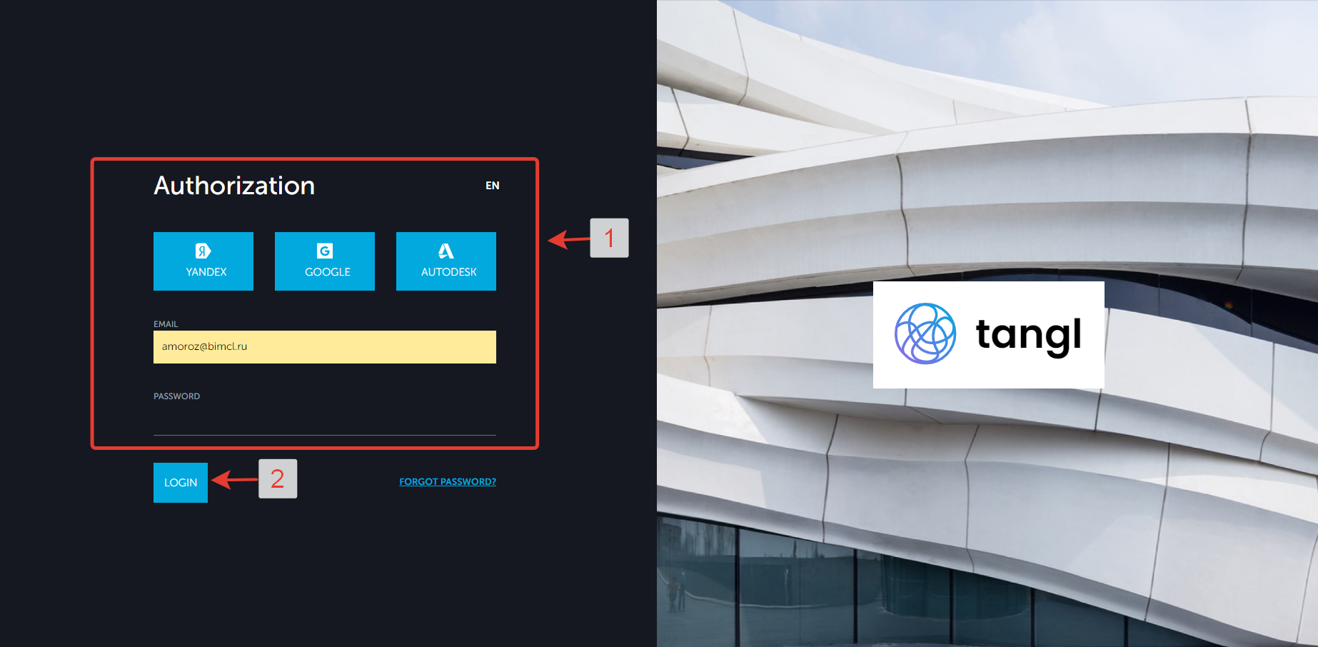
To log in, enter your account details in the login window.
After launching and authorization in the system, you will see the main window of the client. The Inbox field will display all uploaded models of the company.
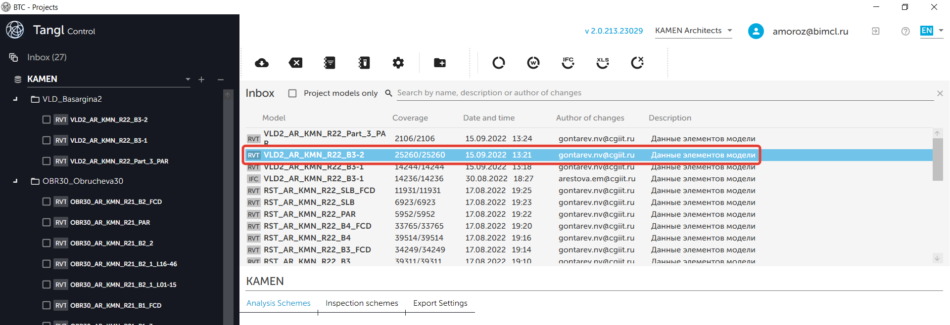
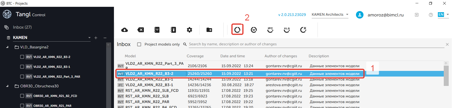
To open the model you can double-click on the line with the model name or click on the Open input data button.
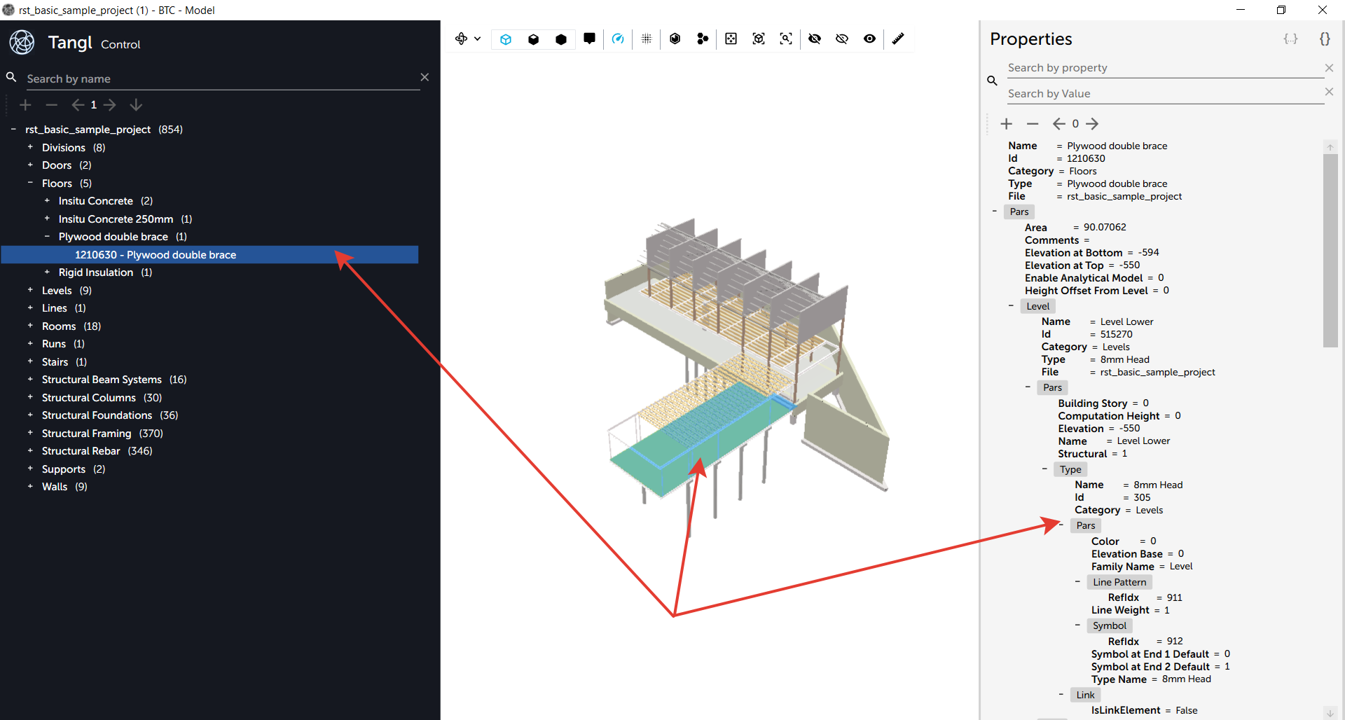
After opening the viewer you will see the structure of the model, the geometry of its elements and also the properties of any selected element. In the viewer you can easily navigate through the model, hide and isolate elements, crop, measure distances with a tape measure, etc.
For a detailed analysis of the Model window, read the article (will be soon).
Now it can be closed.
The creation of a project
In each company many projects can be created. Each project can have its own folder structure in which the results of model analysis are stored.
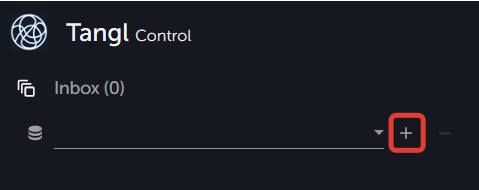
Create your first project and give it a name. Click + next to an empty line.
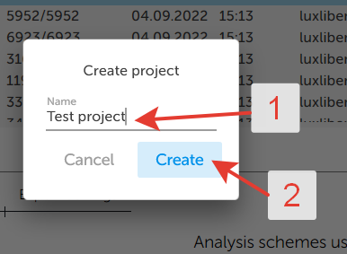
A window will open, enter the name of the project there.
After creation, the project will become active and the button for creating folders will become available.
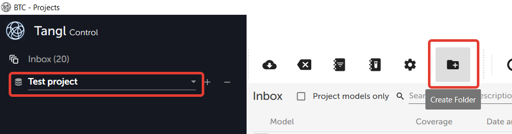
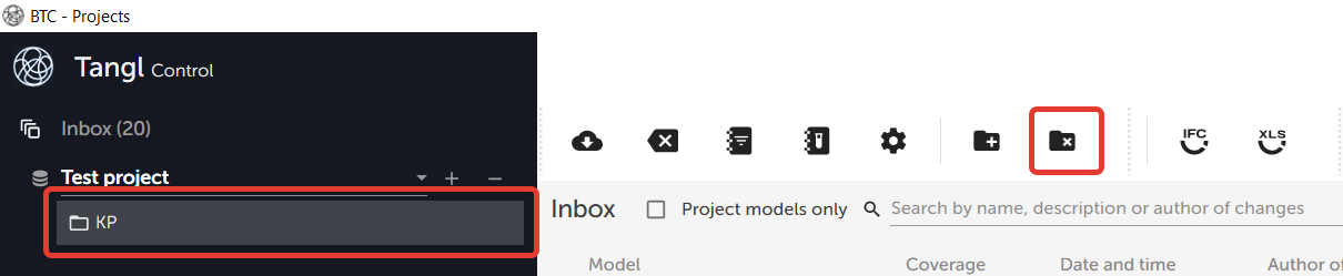
Create a new folder Structural Solutions at the root of the project. It will store the results of the analysis of our model. Once selected, a button for deleting folders will appear.
Control coordinates models through a single pipeline, which includes the selection and validation of individual elements and complex checks of sets of elements (in development).
In order to validate an element and allow it to participate in complex checks, you need to determine first that it is valid and meets all the requirements. To do this it is necessary that it gets into the iterative selection and reaches its end point in one of the positions of the selection directory. After that the position applies a series of checks to it, according to the results of which the element is considered as approved for further use.
In this way the verification process of an individual elements can be divided into a multi-stage selection phase and a checkpoint verification phase if the element has passed all the selection stages to the end.
The creation of a selection directory.
The selection stages are described by the selection directory tree, and the verification stages are described by control points (checks bindings) in each final estimated position.
In addition each position can have different control points. Control points have names.
For our simplest case we need to create a selection directory consisting of several positions.
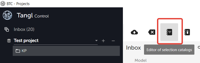
Open the selection directory window.
You will see an empty window with no directories yet.
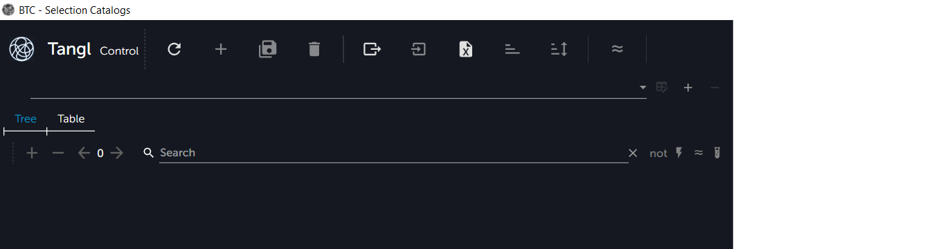
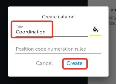
Create the first selection directory by clicking on the + button and enter a name.
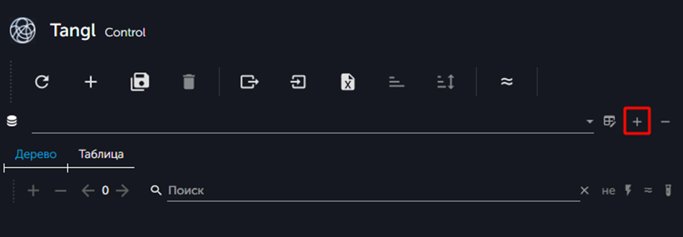
A window will open in which you need to enter the name of the directory.
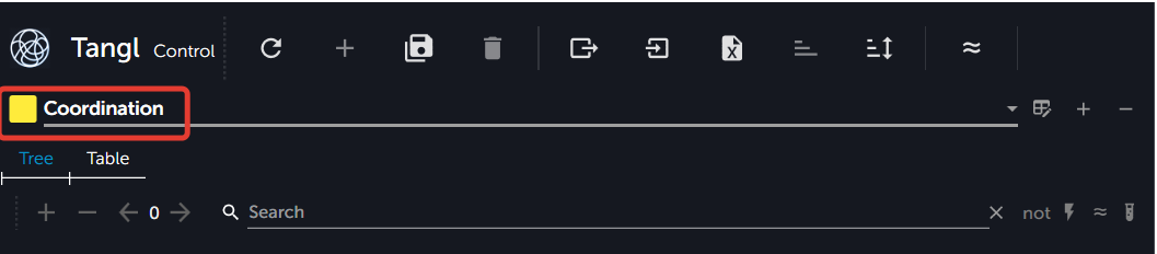
The new empty directory will become active.
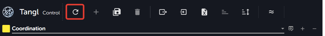
If the directory hasn't appeared, click on the Update directories button.
Creating positions manually.
Usually there are many positions in directories. And therefore they are not created manually, but imported (for example, from Excel). Also, directories usually have groups of parent and child positions, so that it is convenient to work with them. In other words, directories have a tree structure.
Our directory will have a parent position and several child positions.
In Tangl there is no difference between position groups and positions themselves, as in many other systems. Each position can be a parent for other positions (have children).
Create the first root position by clicking on the + button.
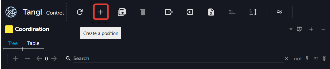
After clicking a window will open, where you need to enter a name.
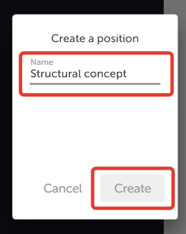
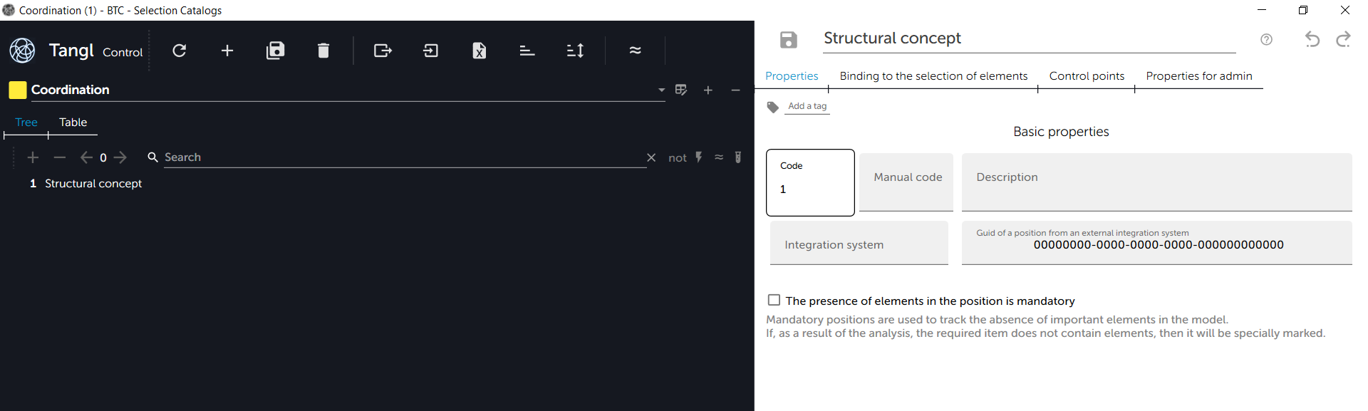
The new root position will appear in the directory and an automatic code will be assigned to it. It can be highlighted. At the same time the Properties area of the selected position in the Classifier will appear in the right part of the window.
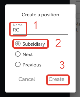
Create a child position: RC (reinforced concrete).
To do this select the root position and press the + button again.
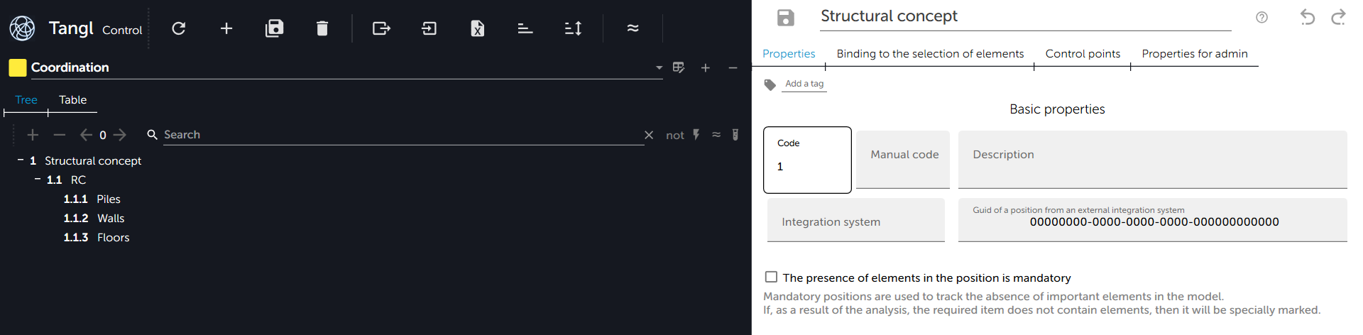
Create child positions for the Monolith position: Piles, Walls, Floors.
After creating the positions, the directory will look like this.
The creation of a selection scheme.
The company can use directories in different variations, which are used for various projects.
The mechanism of calculation schemes allows to create once a set and subordination of used directories and use it to connect in various projects. The mechanism is configured in the company's global settings.
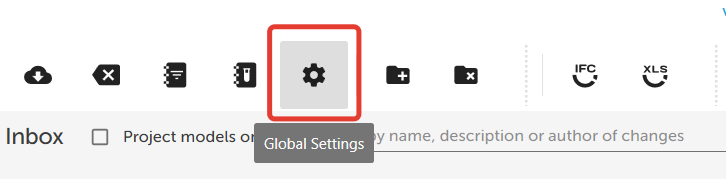
Open the global settings window.
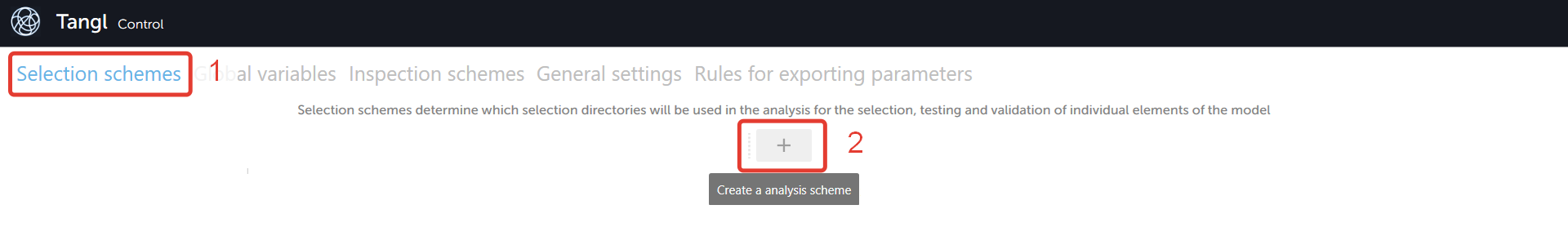
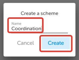
The first settings tab controls selection schemes. Create a new selection scheme and fill in the Scheme name fileld.
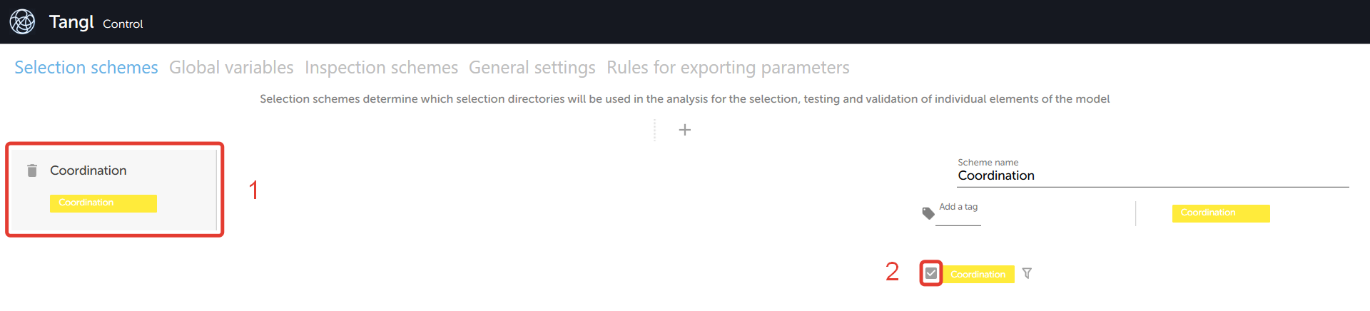
Select the created scheme and enable the use of a single directory in it.
Now this scheme can be activated for our project in the main window of the client.
Click on an empty space in the project navigation window so that the properties appear on the right side of the window, and then activate the scheme. It will be transfered to the left side of the project properties.
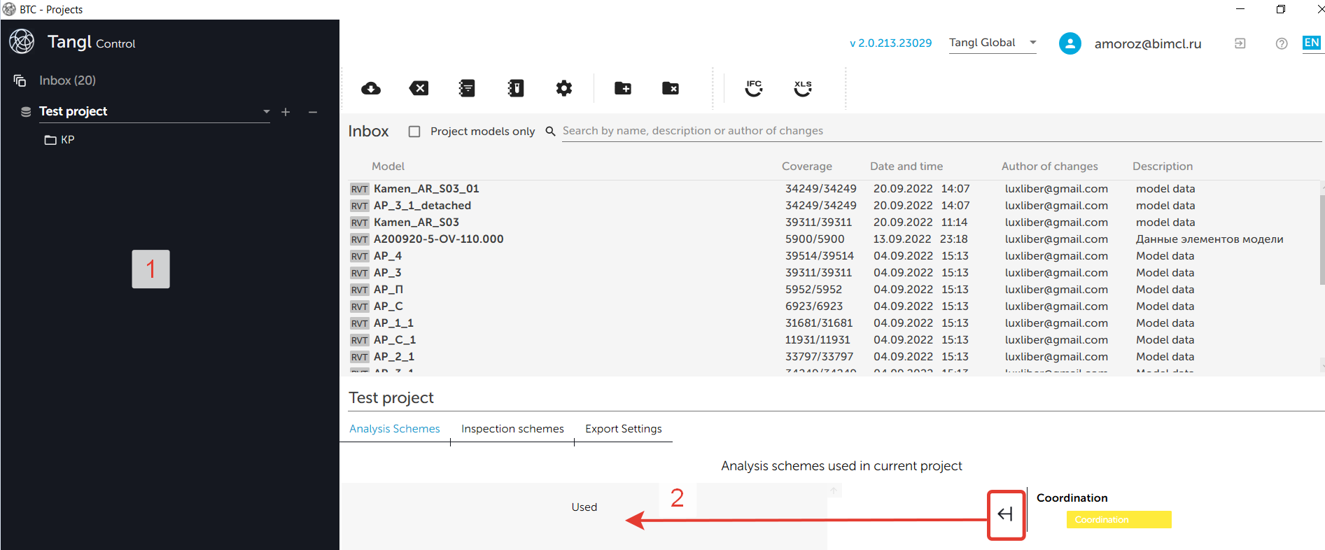
Now, when performing analysis of incoming data, our directory will be used.
The tree structure of the directory makes the selection multi-stage. In this case the root positions of the directory carry out the roughest primary selection, and the child positions work with elements selected by parents and filter them out according to their selection bindings.
Therefore it is very important that each position remembers the list of those objects that it selected and those that it filtered out, so that the user can see all the progress and statistics of the selection.
The exceptions are root positions, because if an element remains unselected in the root position in the first stage, then the cause can not be clearly determined and such element goes into the list of globally unselected objects (which didn't start the selection). Thus, the root positions only remember the list of selected objects.
In order for a position to understand which objects to select, it is necessary to create a selection binding in it.
Formation of selection bindings.
Bindings can be created in Model and Directories windows.
To begin with, let's consider creating a binding in the Models window, because there you can immediately create and test the binding on the model. Such process of creation will be more convenient and faster than through the Directories window.
Formation of a binding in the Model window.
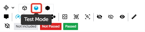
Go to the only model we have. Open the Bindings test panel.
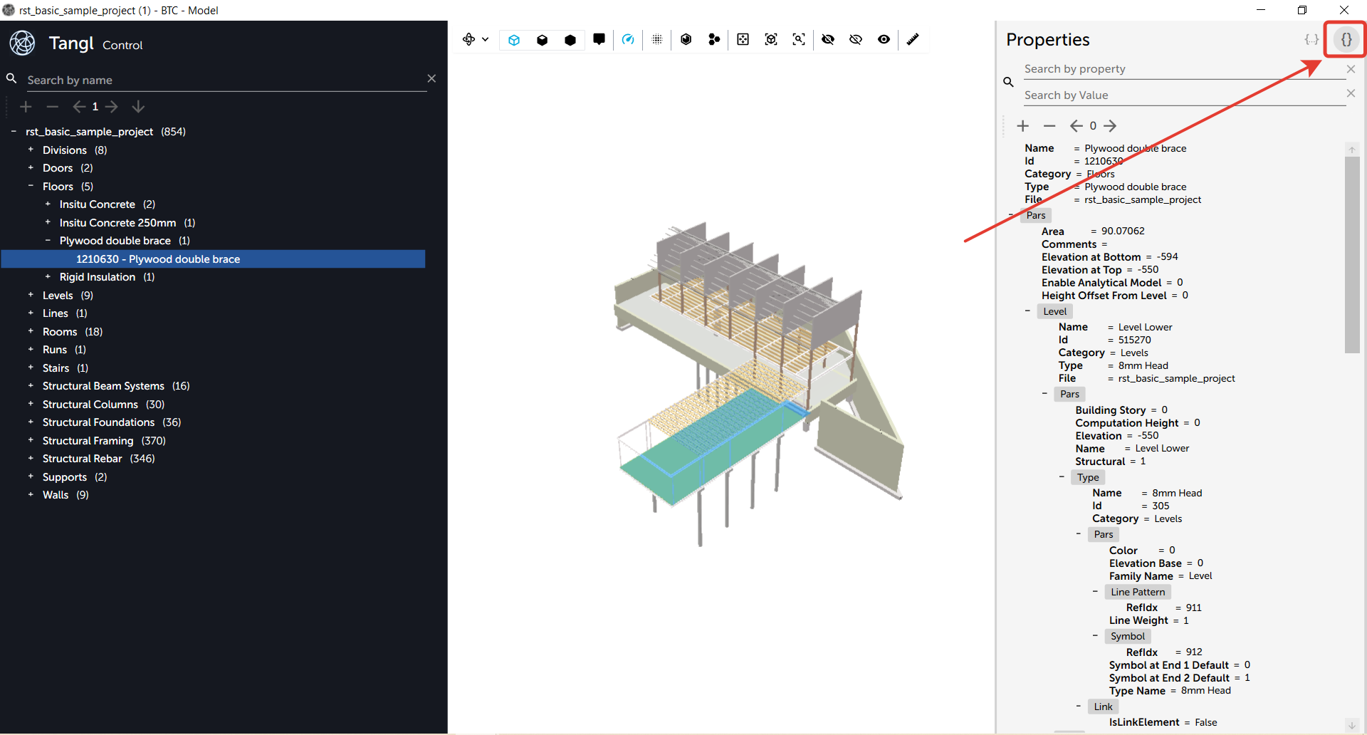
After clicking, the bindings window will open. For convenience you can resize the properties and bindings window using borders.
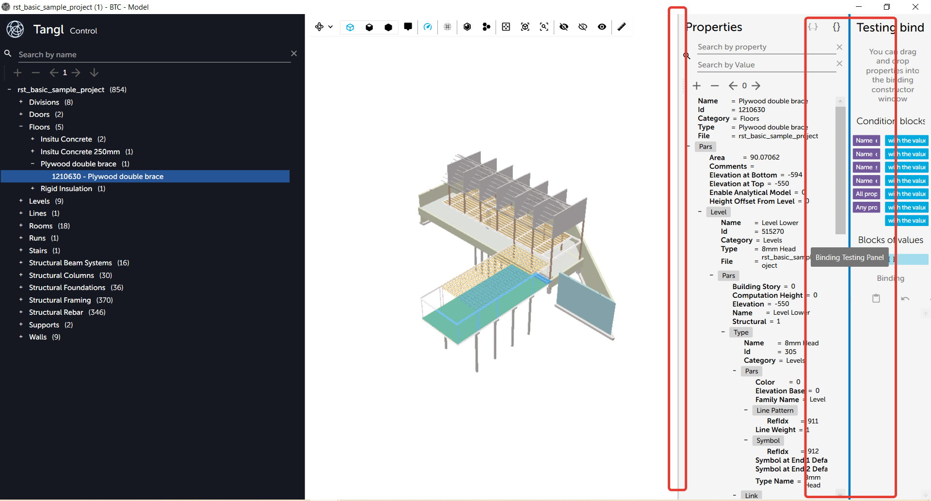
As an example let's create a simple binding, that will find floors.
Hold down the "Name equals" block and drag it to the bottom field.
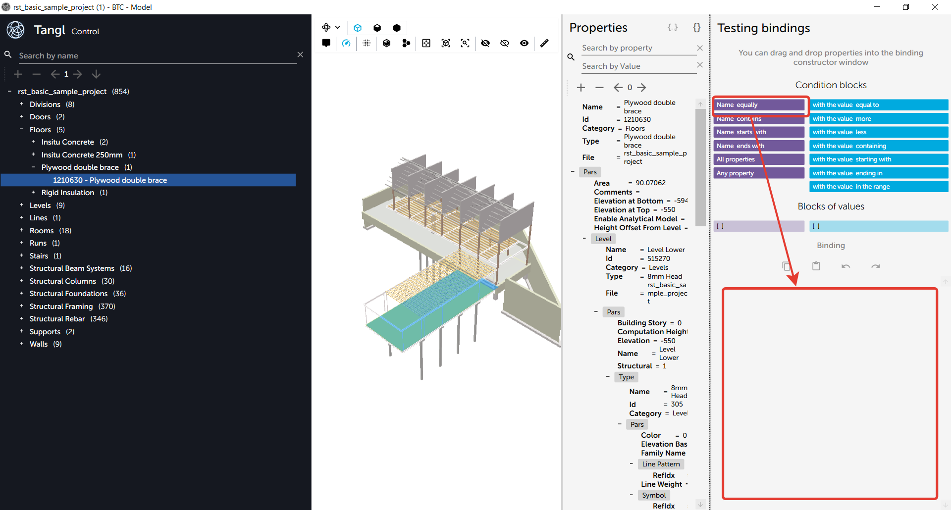
After transfering the block of conditions the following structure will appear:
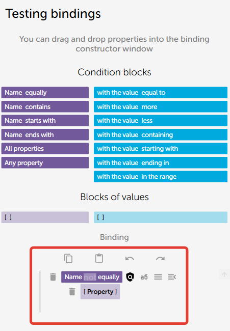
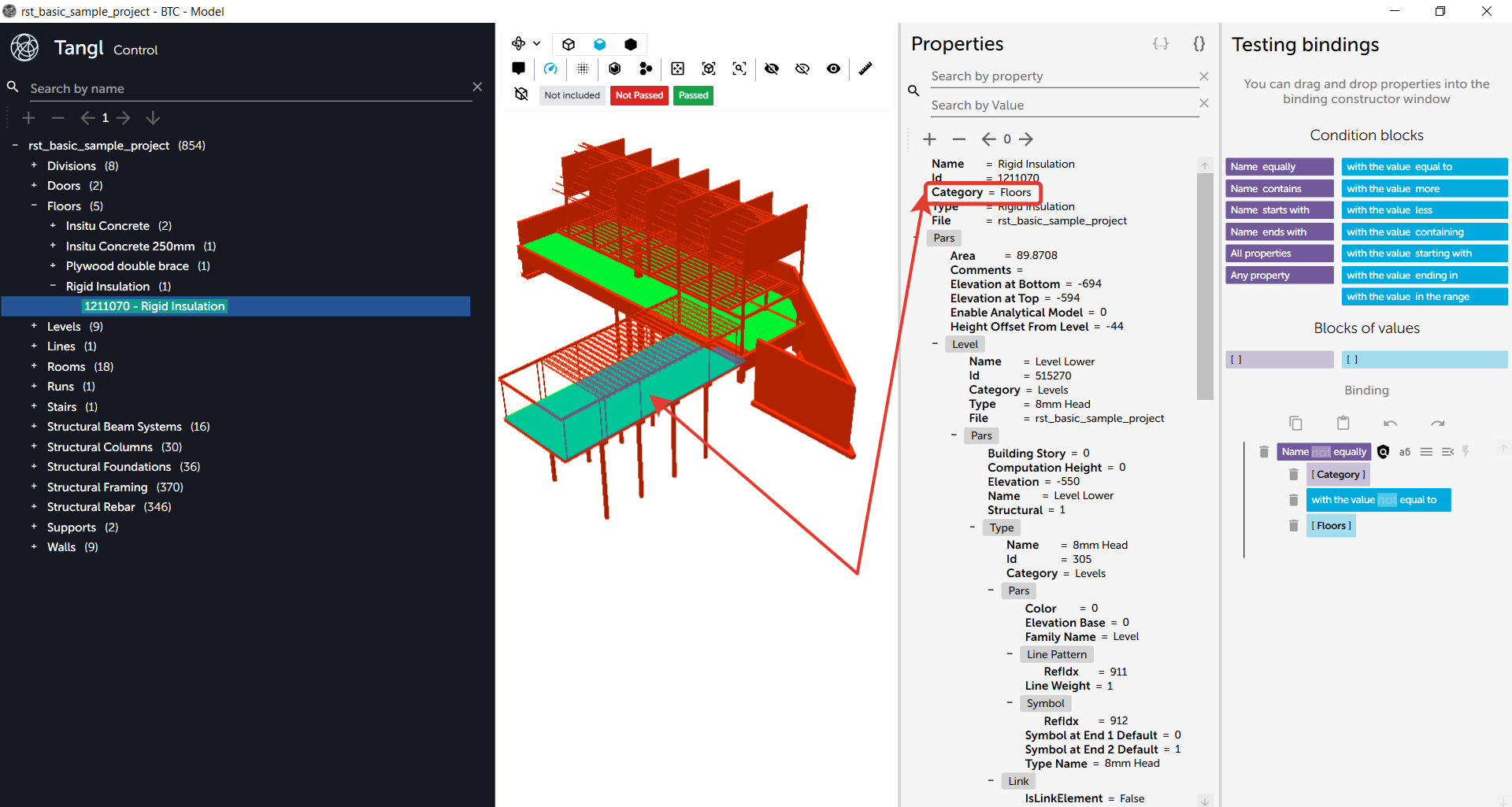
In Property enter what properties to search for. In our case, we write Category.
After that move the condition block with a value equal below the first block.

This structure will appear
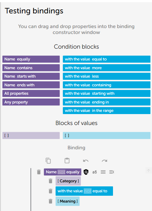
Enter in the Value field that you need to search for Floors.
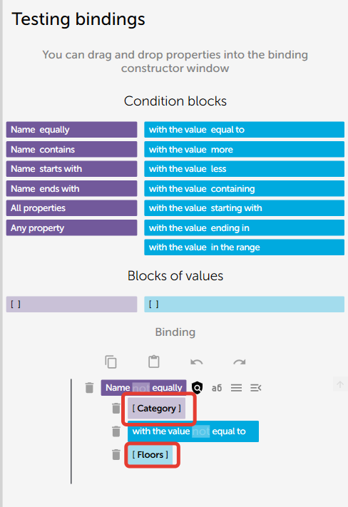
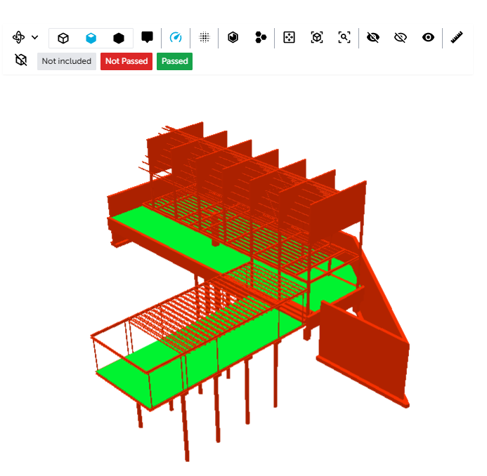
After creating the binding click the Test selection button.
The program will automatically analyze all elements of the model and show which element matches the binding and which does not, using different colours. The viewer will switch to test mode.
You can process only a selected part, not the entire model at once.
To check if the binding worked, we need to select the element that matches our binding and check if the binding worked correctly.
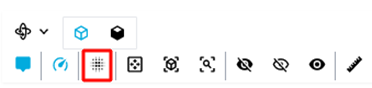
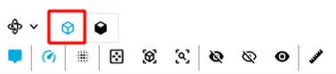
To exit the test mode, we need to change the mode in the toolbar. The test mode is active now.
Switching to the main mode.
Formation of bindings in Directories window.
Formation of binding in "Binding for selection of elements" tab.
Position bindings in this tab are needed to select model elements for testing.
In the Selection directories window bindings are formed in the same way.
Select Structural Solutions position. We will select elements in it.
Make a binding.
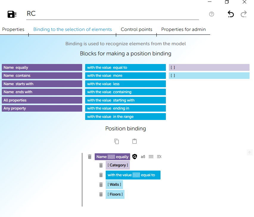
This position will select the elements, specified in the binding.
Make bindings for subpositions.
For walls and floors.
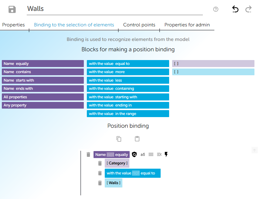
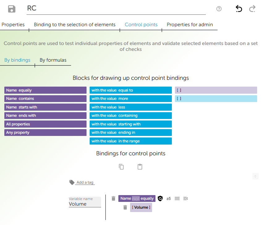
Formation of bindings in the "Control points" tab.
In this tab bindings are needed for composing tests.
Go to the "Control points" tab.
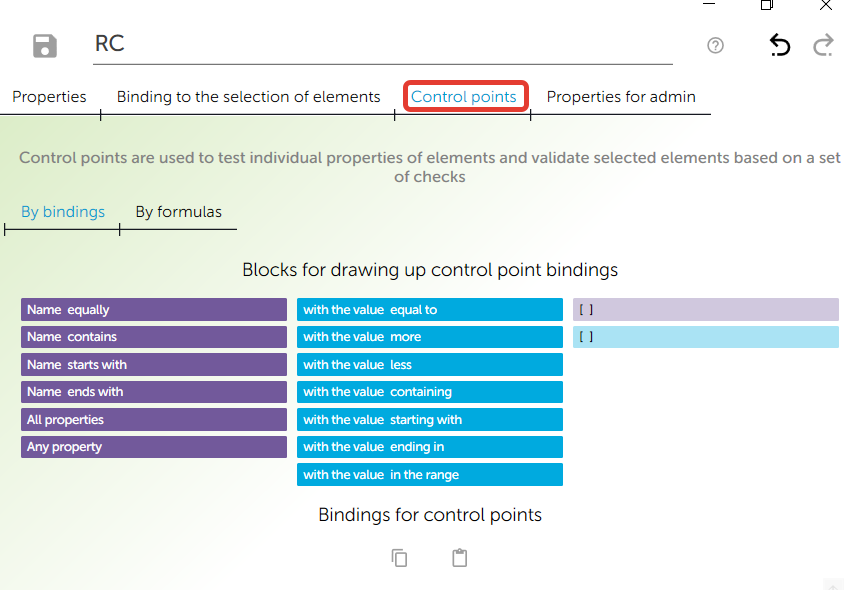
When you create a binding such structure will be built.
In the Variable name field fill in the name by which the test will be performed.
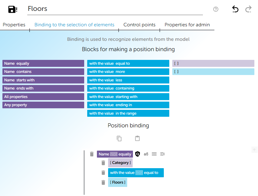
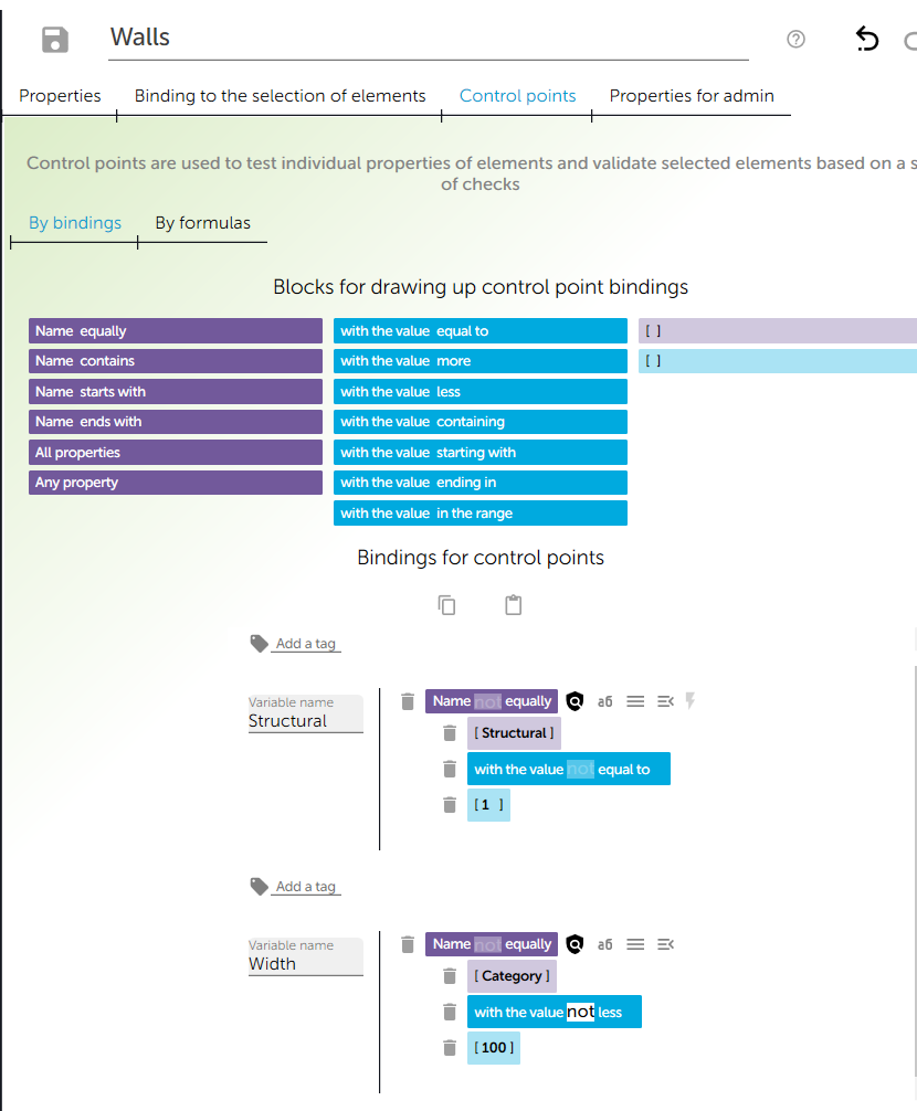
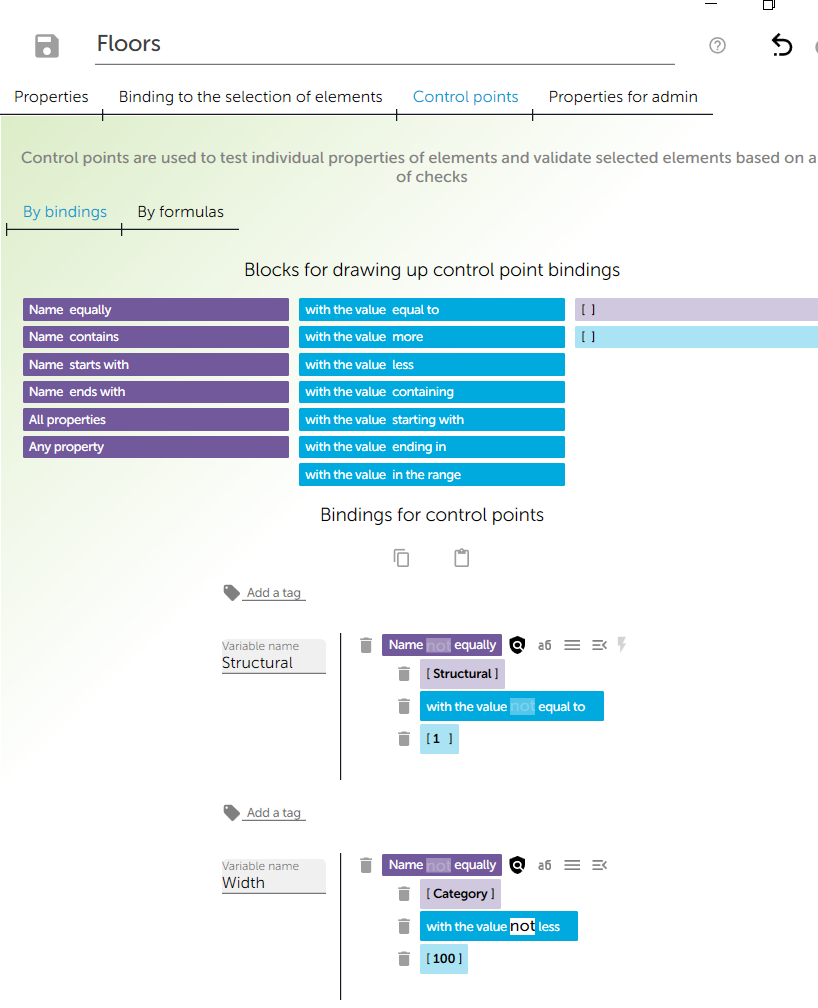
Create a binding in Walls and Floors positions.
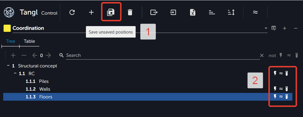
After creating the bindings we need to save the changes by clicking the Save unchanging positions button. **** Icons will appear next to the positions, indicating that the position has a binding.
Starting analysis
It is very easy to make model analysis from the incoming data. Drag the model from the Inbox zone to the desired folder in the project.
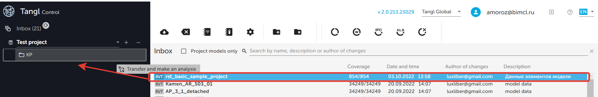
After that the model will appear in the folder. When it is selected, versions of its analysis results will appear in the right part of the window. The list will show both completed results and those that are in progress.
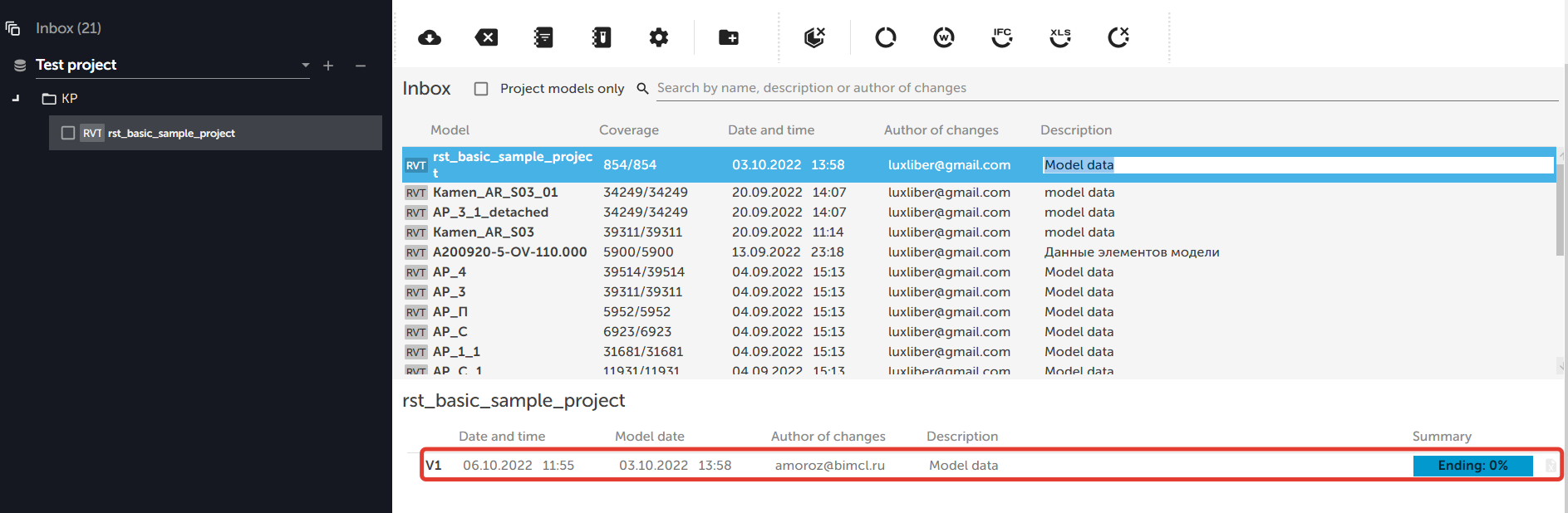
After the analysis is completed, you can see the results.
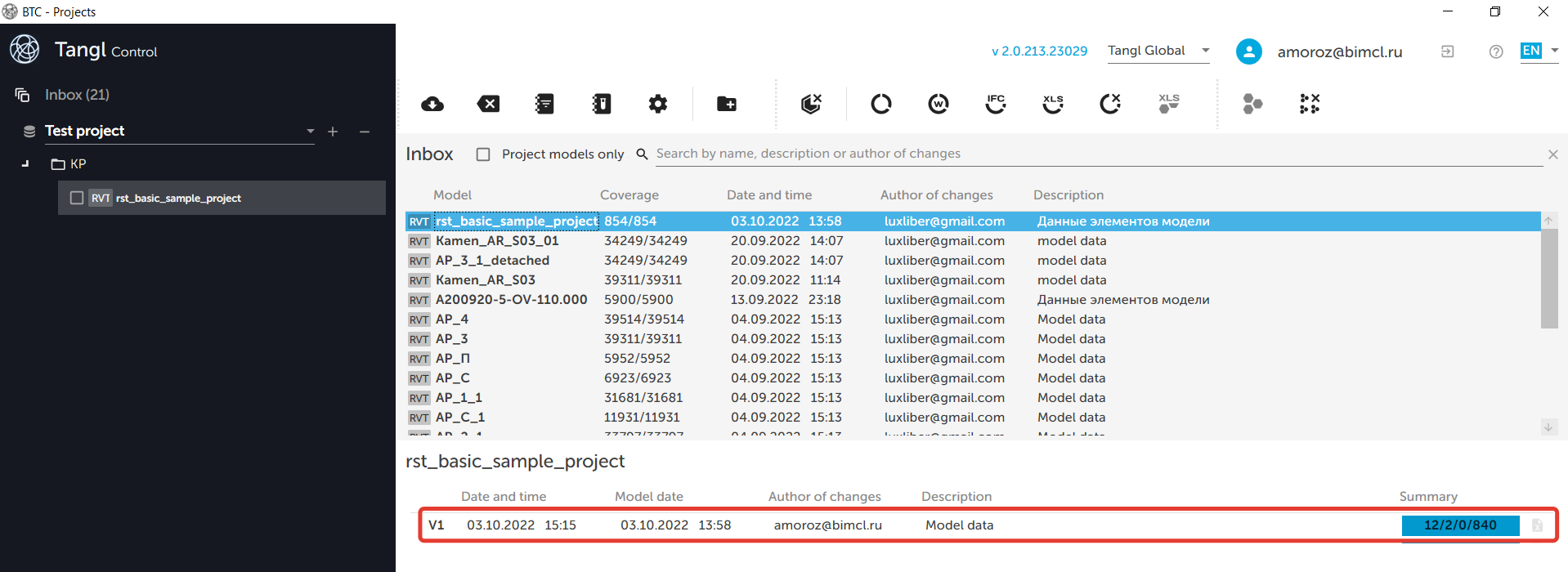
The statistics will show the values of the elements:
- The first digit - elements, that passed all the tests.
- The second digit - elements, that didn't pass all the tests.
- The third digit - elements, that didn't complete the selection.
- The fourth digit - elements, that didn't start the selection.
The result of the analysis is a tree of checks and selections statuses.
To view the analysis of the model, select the finished analysis and click the View the result button.
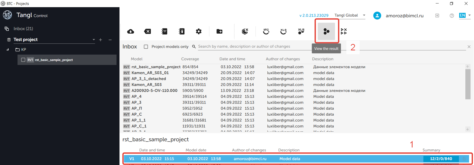
The BTC - analysis results window will open.
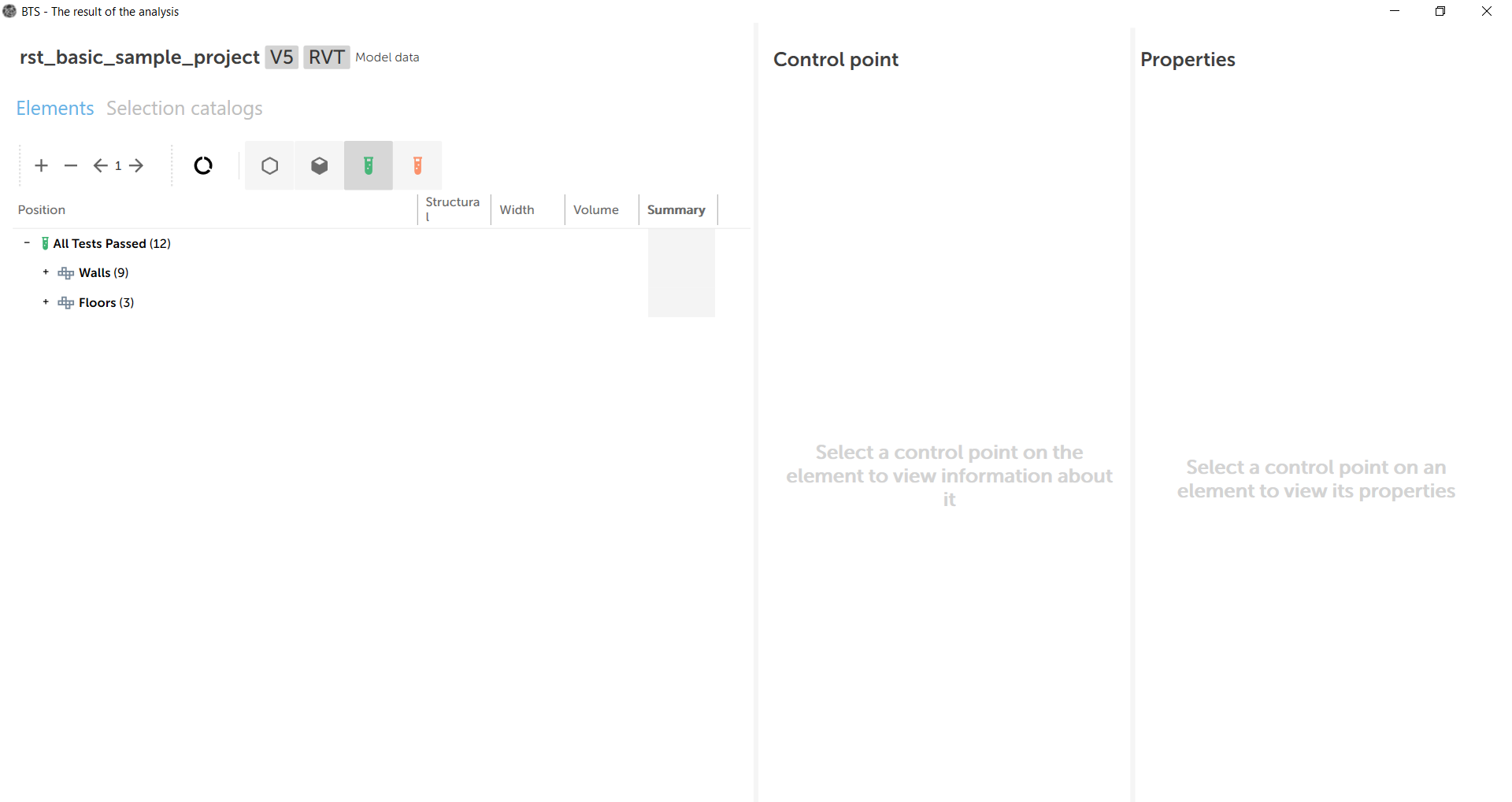
More detailed information you can find in the BTC - analysis result article (will be soon).